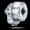
E-Catalog > AUTOGRIP > Rotary Cylinders

PAGE VIEW : 440

Product Information :

Name :
Rotary Cylinders
Category :
  1. เครื่องจักร, อุปกรณ์เกี่ยวกับเครื่องจักร, เครื่องมือกล
Sub - Category :
  1. AUTOGRIP
Brand :
AUTOGRIP CHUCK
Product Type :
  1. สินค้า, ผลิตภัณฑ์

Product Detail :

Rotary Cylinders

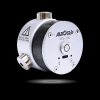
Looking for a reliable supplier of rotary cylinders to enhance your automation processes? AUTOGRIP® has got you covered. Our rotating hydraulic cylinders are specifically designed to work with high-speed rotation of the spindle to drive the clamping and loosening of the chuck, making them an essential component in the automatic clamping configuration.

We offer two types of rotary cylinders, including rotary hydraulic cylinders and rotary air cylinders. Our hydraulic rotary cylinders come equipped with a built-in non-return valve self-locking mechanism, providing the function of central air injection or water injection, depending on the model. They can also be used with a stroke detection mechanism to ensure accurate positioning of the workpiece clamping.


RC
RC
Rotating Joint
New!
RID
RID
Designed for 4th-axis and 5th-axis rotary tables
New!
TK
TK
Thru-Hole
TS
TS
Thru-Hole
TH
TH
Thru-Hole | Hydraulic
TR
TR
Thru-Hole
RA
RA
Non-Thru-Hole | air
RH
RH
Non-Thru-Hole | Hydraulic
RK
RK
Non-Thru-Hole | Hydraulic
RK-N
RK-N
Non-Thru-Hole | Hydraulic
RS
RS
Stroke Control
RS-N
RS-N
Stroke Control
RL
RL
Non-Thru-Hole
RL-N
RL-N
Non-Thru-Hole
RL-AN
RL-AN
Air Connection Rotary Cylinder
RE
RE
Compact Style Rotary Cylinder
RE-A
RE-A
Compact Style Rotary Cylinder


RC


Hydraulic Cylinder with Rotating Joint

Rotating Joint
  • Center through-hole hydraulic cylinder, suitable for horizontal CNC lathes.
  • Can choose an external rotary joint with either single or double paths.
  • It meets the demand for coolant through spindle and airtight pressure detect function.
  • Has a buil-in check valve for safety.
  • Stroke control via proximity switch or linear positioning system.

The proximity switch and single or double paths rotating joint are optional.

Please contact AUTOGRIP for more detailed drawing.

Catalog Download


Specifications

ModelEff. piston area cm2
Extend
Eff. piston area cm2
Retract
Piston stroke
(mm)
Max. speed
min-1(r.p.m.)
Max. pressure
MPa(kgf/cm2)
I
kg‧m2
Weight
(kg)
RC-85 43.8 48.1 20 5000 3.5(35) 0.01 6.8
RC-100 65.6 64.4 20 5000 3.5(35) 0.02 9.2
RC-125 109.8 108.5 25 5000 3.5(35) 0.03 11.1
RC-145 152.2 143.9 30 5000 3.5(35) 0.03 14.6
RC-200 279.3 273.6 35 4000 4.0(40) 0.26 35.5
RC-250 451.1 436 60 2000 5.0(50) 0.57 57.3


Dimensions

* Subject to technical changes.

MODELABC1C2DE(h7)FG1max.G1min.G2max.G2min.HJKL1L2M H8M1NPP1QQ1RS H6TUV1V2W1W2
RC-85 85 20 120 116 100 65 32 45 25 28 8 76.5 156.5 M24x1.5 6~M8x80 12.5 25.4 10 40 23.5 14 4 3 38 56 110 RC3/8 31 M4x10 48 M5x9
RC-100 100 20 135 131 115 80 40 45 25 28 8 72 158.5 M30x1.5 6~M8x75 12.5 32 10 50 23.5 14 4 3 38 56 110 RC3/8 31 M4x10 48 M5x9
RC-125 125 25 160 156 140 110 40 50 25 33 8 78 164 M30x1.5 6~M8x80 11 32 10 50 23.5 14 4 3 38 56 110 RC3/8 31 M4x10 48 M5x9
RC-145 145 30 187 183 165 110 50 55 25 38 8 83 169.5 M40x1.5 6~M10x90 16.5 42 12 57 23.5 14 4 3 38 56 110 RC3/8 31 M4x10 48 M5x9
RC-200 195 35 257 257 225 120 55 73 38 51.5 16.5 120.5 222.5 M36x4.0 6~M16x130 26 38 12 65 35 15 6.5 4 48 74 135 RC1/2 35 M4x10 60 M5x11
RC-250 245 60 307 305 275 160 65 85 25 76.5 16.6 171.5 268.5 M42x3.0 6~M16x180 26 45 12 65 35 15 6.5 4 48 74 135 RC1/2 35 M4x10 60 M5x11

* The proximity switch and rotary joiint are optional. Choose and attach the appropriate type. Please contact AUTOGRIP for more detailed drawing.


Download

Model 2D pdf 2D dwg 3D step
RC-85      
RC-100      
RC-125      
RC-145      
RC-200      
RC-250      
 

RID


Rotary Hydraulic Cylinder for 4th & 5th Axis

for 4th & 5th Axis

RID Rotary Hydraulic Cylinder is specially designed for 4th-axis and 5th-axis rotary tables. Featuring an ultra-short and lightweight structure, it helps save installation space and is ideal for compact machining environments.

With a drain-free design, no oil return piping is required, simplifying machine integration and reducing installation complexity.

Suitable for precision indexing applications, RID delivers stable hydraulic transmission performance, making it an ideal solution for multi-axis machining and automation clamping systems.


Features
  • Ultra-short and lightweight design
  • Designed for 4th-axis and 5th-axis rotary tables
  • Drain-free design eliminates oil return piping
  • Ideal for limited installation spaces
  • Stable hydraulic performance for precision machining


Note:This series is not suitable for direct installation on horizontal or vertical lathes.


Specifications

ModelEff. piston area cm2
Extend
Eff. piston area cm2
Retract
Piston stroke
(mm)
Max. speed
min-1 (r.p.m.)
Max. pressure
MPa (kgf/cm2)
I
kg‧m 2
Moment of inertia
Total oil leakage 
lit./min.
Weight
(kg)
RID-80N 49.3 44.3 15 60 35 - - 4.6
RID-100N 77.5 70.5 21 60 35 - - 6.5


Dimensions

* Subject to technical changes.

ModelA
I.D.
BB1CD
h7
EF
H8
G maxG minHJKLL1MM1NPQRSTUV
RID-80N 80 112 118 100 30 25 18 56.5 41.5 52 23 91 6-M6x55 11 M16x2 30 5 4 16 11 85 M6x10 76 RC 1/4
RID-100N 100 132 138 119 36 30 21 66.5 45.5 58 23 97 6-M6x60 10 M20x2.5 35 5 4 16 11 85 M6x10 76 RC 1/4


Download

Model 2D pdf 2D dwg 3D step
RID-80N      
RID-100N      


TK


Short type Thru-Hole Hydraulic Rotary Cylinder with Safety Device

Short Type Thru-hole | Hydraulic

The AUTOGRIP Compact Thru-Hole Hydraulic Rotary Cylinder features an ultra-short body measuring only approximately two-thirds the length of conventional models, making it ideal for CNC lathes and automated machines with limited installation space.

Its large thru-hole design accommodates bar stock and long workpieces, while the built-in check valve locking mechanism and pressure relief valve enhance operational safety and clamping reliability. An optional linear position sensing system is available to support automation and smart manufacturing applications.

Features

  • Ultra-compact design, only approximately 2/3 the length of conventional cylinders.
  • Large thru-hole for bar feeding and long workpieces.
  • Built-in check valve locking mechanism and pressure relief valve.
  • Rear mounting design for easy installation.
  • Optional linear position sensing system available

Linear sensor can be attached.(optional)

Catalog Download


Specifications

ModelEff. piston area
cm2
Extend
Eff. piston area
cm2
Retract
Piston stroke
(mm)
Max. speed
min-1(r.p.m.)
Max. pressure
MPa(kgf/cm2)
I
kg‧m2
Weight
(kg)
Total oil leakage
lit./min
TK-A528 73 69.7 12 8000 4.5 (45) 0.012 6.2 3
TK-A533 73 69.7 12 8000 4.5 (45) 0.012 6 3
TK-C643 99.1 88.0 15 7000 4.5 (45) 0.018 7.5 3
TK-A646 105.0 93.9 15 7000 4.5 (45) 0.018 7.3 3
TK-B646 105.0 93.9 15 7000 4.5 (45) 0.018 8.6 3
TK-C646 99.1 88.0 15 7000 4.5 (45) 0.018 7.5 3
TK-B846 135.3 125.0 20 6300 4.5 (45) 0.032 12.4 3.9
TK-A853 135.3 125.0 20 6300 4.5 (45) 0.032 11.8 3.9
TK-B853 135.3 125.0 20 6300 4.5(45) 0.032 11.7 3.9
TK-A1068 170.1 155.3 25 5500 4.5(45) 0.065 19.2 4.2
TK-A1075 170.1 155.0 25 5500 4.5(45) 0.065 18.8 4.2
TK-A1078 170.1 155.3 25 5500 4.5(45) 0.065 17.4 4.2
TK-A1287 234 217.5 30 3800 4.0 (40) 0.092 24.8 4.5
TK-A1291 234 217.5 30 3800 4.0 (40) 0.092 24.8 4.5
TK-A1511 336.4 315.2 30 3000 3.5(35) 0.38 57.9 7
TK-A1512 336.4 315.2 30 3000 3.5(35) 0.38 53.8 7
TK-A1512-35 336.4 315.2 35 3000 3.5(35) 0.38 53.8 7
TK-2114 373.2 336.1 35 2500 3.0 (30) 0.54 58.2 8
TK-2416 418.4 375.4 35 2000 3.0 (30) 1.12 78 9
TK-2416L 418.4 375.4 51 2000 3.0 (30) 1.31 79.2 9
TK-2820 526.2 472.6 51 1600 3.0 (30) 2.4 134 10


Dimensions

* Subject to technical changes.

ModelA
I.D.
BCDE
h7
FG1max.G1minG2max.G2minHJKLL1L2M1M2M3N1N2N3O1
H8
O2
H8
PQ1Q2Q3R
g7
S
H7
TUVW1W2X1X2Y1Y2Z
TK-A528 105 141 125 125 110 45 12 0 38 26 49 77.5 123 6~M10x20 M8x55 14 M38x1.5 25 13 M39x1.5 25 8 35 28 79 8.5 30 RC1/4 37 62 70 98 6 62 110 49 M6x6 83 M5x6 5
TK-A533 105 141 125 125 110 45 12 0 38 26 49 77.5 123 6~M10x20 M8x55 14 M38x1.5 25 13 M39x1.5 25 8 35 33 79 8.5 30 RC1/4 37 62 70 98 6 62 110 49 M6x6 83 M5x6 5
TK-C643 128 156 140 140 120 65 15 0 44 29 56 85 125 12~M10x20 M8x60 12 M50x2 25 13 M52x1.5 29 9 45 43 87 8.5 36 RC3/8 50 76 85 116 9.5 74 120 64 M6x10 98 M5x6 5
TK-A646 128 162 147 147 130 65 15 0 44 29 56 85 125 12~M10x20 M8x60 12 M55x2 25 13 M52x1.5 29 9 50 46 87 8.5 36 RC3/8 50 76 85 116 9.5 74 120 64 M6x10 98 M5x6 5
TK-B646 128 162 130 147 100 65 15 0 44 29 66 95 135 12~M10x20 M8x70 12 M55x2 30 15 M52x1.5 29 9 50 46 97 8.5 36 RC3/8 50 76 85 116 9.5 74 120 64 M6x10 98 M5x6 5
TK-C646 125 156 140 140 120 65 15 0 44 29 56 85 125 12~M10x20 M8x60 12 M55x2 25 13 M52x1.5 29 9 50 46 87 8.5 36 RC3/8 50 76 85 116 9.5 74 120 64 M6x10 98 M5x6 5
TK-B846 145 185 170 165 130 70 20 0 48 28 66 95 135 12~M10x20 M8x70 12 M55x2 30 15 M58x1.5 30 8 50 46 97 8.5 36 RC3/8 56 85 96 128 11.5 79 130 73 M6x12 110 M6x6 5
TK-A853 145 185 170 165 140 70 20 0 48 28 66 95 135 12~M10x20 M8x70 12 M60x2 30 15 M58x1.5 30 8 55 53 97 8.5 36 RC3/8 56 85 96 128 11.5 79 130 73 M6x12 110 M6x6 5
TK-B853 145 185 170 165 130 70 20 0 48 28 66 95 135 12~M10x20 M8x70 12 M60x2 30 15 M58x1.5 30 8 55 53 97 8.5 36 RC3/8 56 85 96 128 11.5 79 130 73 M6x12 110 M6x6 5
TK-A1068 170 212 190 190 160 95 25 0 50 25 74 108 158 12~M10x20 M10x80 16 M75x2 35 15 M84x2 34 9 70 68 110 12 40 RC1/2 81 108 121 164 10 98 160 98 M6x12 155 M6x8 5
TK-A1075 170 212 190 190 160 95 25 0 50 25 74 108 158 12~M10x20 M10x80 16 M85x2 35 15 M84x2 34 9 80 75 110 12 40 RC1/2 81 108 121 164 10 98 160 98 M6x12 155 M6x8 5
TK-A1078 170 212 190 190 160 95 25 0 50 25 74 108 158 12~M10x20 M10x80 16 M87x2 35 15 M84x2 34 9 82 78 110 12 40 RC1/2 81 108 121 164 10 98 160 98 M6x12 155 M6x8 5
TK-A1287 200 245 215 225 180 110 30 0 59 29 86 126 184 M12x24 M10x90 14.5 M95x2 35 15 M99x2 38 9 90 87 127.5 15 45 RC1/2 96 120 138 180 7 110 185 108 M6x10 165 M6x10 5
TK-A1291 200 245 215 225 180 110 30 0 59 29 86 126 184 M12X24 M10x90 14.5 M100x2 35 15 M99x2 38 9 95 91 127.5 15 45 RC1/2 96 120 138 180 7 110 185 108 M6x10 165 M6x10 5
TK-A1511 250 300 275 275 230 140 30 0 58 28 102 156 226 M16X36 M12x110 21 M120x2 45 15 M129x2 38 9 115 110 153.75 17 50 RC1/2 126 150 170 227 7 134 210 138 M6x10 210 M6x9 6
TK-A1512 250 300 275 275 230 140 30 0 58 28 102 156 226 M16X36 M12x110 21 M130x2 45 15 M129x2 38 9 125 120 153.75 17 50 RC1/2 126 150 170 227 7 134 210 138 M6x10 210 M6x9 6
TK-A1512-35 250 300 275 275 230 140 35 0 63 28 102 161 231 M16x36 M12x115 21 M130x2 45 15 M129x2 38 9 125 120 158.75 17 50 RC1/2 126 150 170 227 7 134 210 138 M6x10 210 M6x9 6
TK-2114 265 320 295 295 240 165 35 0 60 25 115 173.5 247.5 M16X36 M12x120 17.5 M155x2 45 20 M149x2 38 9 145 140 170 17 50 RC1/2 146 170 190 250 7 145 210 160 M6x10 230 M6x10 6
TK-2416 290 340 300 - 260 190 35 0 60 25 129 185.5 275 M16x32 - - M180x3 45 20 M174x2 38 - 170 166 186.5 20 50 RC1/2 171 202 220 292 7 167 250 188 M6x11 260 M6x12 5
TK-2416L 290 340 300 - 260 190 51 0 76 25 145 201.5 291 M16x32 - - M180x3 45 20 M174x2 52 - 170 166 202.5 20 50 RC1/2 171 202 220 292 7 167 250 188 M6x11 260 M6x12 6
TK-2820 340 395 360 - 320 235 51 0 76 25 152 212.5 316 M20x40 - - M220x3 45 20 M218x2 52 - 210 205 216 21 50 RC1/2 215 262 285 360 7 202.5 300 240 M6x12 320 M6x12 6


Download

Model 2D pdf 2D dwg 3D step
TK-A528      
TK-A533      
TK-C643      
TK-A646      
TK-B646      
TK-C646      
TK-B846      
TK-A853      
TK-B853      
TK-A1068      
TK-A1075      
TK-A1078      
TK-A1287      
TK-A1291      
TK-A1511      
TK-A1512      
TK-A1512-35      
TK-2114      
TK-2416      
TK-2416L      
TK-2820      


Applications

CL COLLET CHUCK Clamping Actuation


TS


Short Type Rotary Hydraulic Cylinder with Big-bore Thru-Hole and Safety Device

Thru-Hole | Super large Through-Hole
  • Bigger bore through-hole design.
  • Super short form, light weighted.
  • Built-in safety check valves and pressure relief valves.
  • Front/Rear end mounting.
  • Diameter of coolant collector’s drain port is optional. Default : Ø33 ; optional : Ø40, Ø60.

Diameter of coolant collector’s drain port is optional. Default : Ø33 ; optional : Ø40, Ø60.

Catalog Download


 Specifications

Model Eff. piston area cm2
Extend
Eff. piston area cm2
Retract
Piston stroke
(mm)
Max. speed
min-1 (r.p.m.)
Max. pressure
MPa (kgf/cm2)
I
kg‧m 2
Weight
(kg)
Total oil leakage
lit./min.
TS-539 72.4 67.1 15 8000 4.5(45) 0.012 6.9 3.0
TS-866 168 155.5 25 5600 4.5(45) 0.056 16.3 4.0
TS-1081 189.2 174.3 25 4800 4.5(45) 0.085  21.2 4.3
TS-1210 231.7 222.0 30 3500 3.5(35) 0.193 35.6 6.0


Dimensions

* Subject to technical changes.

Model A
(I.D.)
B B1 C D E
(h7)
F G1
max.
G1
min.
G2
max
G2
min.
H J K L L1 L2 M1 M2 M3 N1 N2 N3 O1
(H8)
O2
(H8)
P Q1 Q2 Q3 R
(g7)
S
(H7)
T U V W1 W2 X1 X2 Y1 Y2 Z
TS-539 107 143 141 125 125 110 52 15 0 42.5 27.5 57 91 124 6~M10x20 M8x60 12 M45x1.5 25 12 M44x1.5 26 8 42 39 85 8.5 30 RC1/4 42 69 72 103 1


RDL


DOUBLE ROD ROTATING CYLINDER 
WITH EXTERNAL ROTATING JOINT

ROTATING JOINT TYPE
  • Short type, lightweight, dual-rod dual-circuit rotary hydraulic cylinder with
    rotary joint.
  • The internal tie rod can be applied to drive center ejection of parts or power chucks with axial telescopic positioning.
  • The front and rear cylinders are controlled by separate circuits, each
    equipped with Built-in safety check valves .
  • The central through-hole is used for the passage of coolant, oil, or air, and
    can be fitted with an external single-channel rotary joint.

The rotary joint and support frame are options.


Specifications

ModelEff. piston area cm2
Extend
A
Eff. piston area cm2
Retract
B
Eff. piston area cm2
Extend
A
Eff. piston area cm2
Retract
B
Piston stroke
(mm)
Max. speed
min-1 (r.p.m.)
Max. pressure
MPa (kgf/cm2)
I
kg‧m 2
Weight
(kg)
RDL-160S 68.3 190.6 68.3 172.8 25/55 4000 5.0(50) 0.025 26


Dimensions

* Subject to technical changes.

ModelABCDE(h7)FF1G
max.
G
min.
G1
max.
G1
min.
G2
max.
G2
min.
HH1JKK1LM1(H8)M2(h7)NN1PQ
RDL-160S 100 160 210 180 145 60 30 65 40 70 15 41 16 139 201 323 M45x1.5 M20x2.5 M12x29 47 22 45 43 16 66


Download

Model 2D pdf 2D dwg 3D step
RDL-160S      


RD-N


Double-rod Rotary Hydraulic Cylinder

Non-Thru-Hole | Hydraulic
  • For short form, lightweight, double rod rotary cylinder.

The drain port should be independently connected to the oil tank to avoid back pressure.


Specifications

ModelEff. piston area cm2
Extend
A
Eff. piston area cm2
Retract
B
Eff. piston area cm2
Extend
A
Eff. piston area cm2
Retract
B
Piston stroke
(mm)
Max. speed
min-1 (r.p.m.)
Max. pressure
MPa (kgf/cm2)
I
kg‧m 2
Weight
kg
RD-120N 122.7 126.1 116.1 113.1 20 5000 3.0(30) 0.14 11.2
RD-125N 122.7 126.1 116.1 113.1 25 5000 3.0(30) 0.15 11.4


Dimensions

* Subject to technical changes.

ModelABCDE
max.
E
min.
F
max.
F
min.
RD-120N 125 130 137 214 60 40 35 15
RD-125N 125 130 147 224 55 30 35 10


Download

Model 2D pdf 2D dwg 3D step
RD-120N      
RD-125N    


RD


Double-rod Hydraulic Rotating Cylinder with Safety Device

Non-Thru-Hole | Hydraulic

The main advantage of using a hydraulic rotating cylinder is that it allows for precise and controlled movement in a range of industrial and commercial applications. Because the rotating hydraulic cylinder is powered by pressurized fluid, it can exert a large amount of force while remaining relatively compact in size. Additionally, the use of a rotary actuator allows for rotation in a specific direction, which can be beneficial in certain applications. Other advantages include durability, ease of maintenance, and flexibility in design. Overall, hydraulic rotating cylinders can help improve efficiency, accuracy, and productivity in various industries.

  • For short form, lightweight, double rod rotary cylinder.
  • Built-in safety check valves and pressure relief valves.
  • The drain port should be independently connected to the oil tank to avoid back pressure.


Specifications

ModelEff. piston area cm2
Extend
A
Eff. piston area cm2
Retract
B
Eff. piston area cm2
Extend
A
Eff. piston area cm2
Retract
B
Piston stroke
(mm)
Max. speed
min-1 (r.p.m.)
Max. pressure
MPa (kgf/cm2)
I
kg‧m 2
Weight
kg
RD-120 122.7 126.1 116.1 113.1 20 5000 3.0(30) 0.14 11.3
RD-125 122.7 126.1 116.1 113.1 25 5000 3.0(30) 0.15 11.5


Dimensions

* Subject to technical changes.

ModelABCDE
max.
E
min.
F
max.
F
min.
RD-120 125 130 137 227 60 40 35 15
RD-125 125 130 147 237 55 30 35 10


Download

Model 2D pdf 2D dwg 3D step
RD-120      
RD-125    


Other Product In Group "AUTOGRIP (9)"