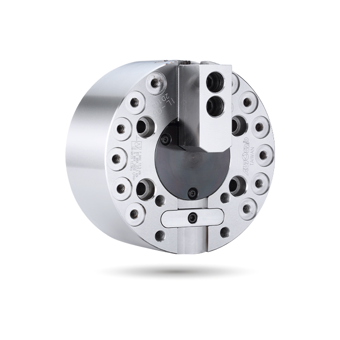
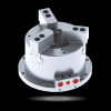
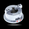
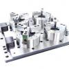
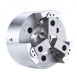
Autogrip® is a well-known brand power chuck manufacturer in Taiwan. Since 1989, we have worked with numerous machine builders around the world. Our power chucks category features various types such as thru-hole, non-thru-hole, large-thru-hole, long jaw stroke, and vertical lathe power chucks, providing our customers with exceptional flexibility and adaptability. We also offer jaw chucks with different configurations ranging from 1, 2, 3, 4, and 6 jaws power chucks, professionally customized and made to order for your lathe power chucks service. The V series power chucks can handle workpieces up to 2,000mm (79”) in diameter.
Autogrip® เป็นแบรนด์ผู้ผลิตหัวจับชิ้นงานไฟฟ้าที่มีชื่อเสียงในไต้หวัน นับตั้งแต่ปี 1989 เราได้ร่วมงานกับผู้ผลิตเครื่องจักรจำนวนมากทั่วโลก กลุ่มผลิตภัณฑ์หัวจับชิ้นงานไฟฟ้าของเรามีหลากหลายประเภท เช่น หัวจับแบบรูทะลุ หัวจับแบบไม่มีรูทะลุ หัวจับแบบรูทะลุขนาดใหญ่ หัวจับแบบช่วงชักยาว และหัวจับสำหรับเครื่องกลึงแนวตั้ง ซึ่งช่วยให้ลูกค้าของเรามีความยืดหยุ่นและปรับตัวได้อย่างยอดเยี่ยม นอกจากนี้เรายังมีหัวจับแบบกรามที่มีการกำหนดค่าต่างๆ ตั้งแต่ 1, 2, 3, 4 และ 6 กราม ซึ่งสามารถปรับแต่งและผลิตตามสั่งได้อย่างมืออาชีพสำหรับบริการหัวจับชิ้นงานไฟฟ้าของเครื่องกลึงของคุณ หัวจับไฟฟ้าซีรีส์ V สามารถรองรับชิ้นงานที่มีเส้นผ่านศูนย์กลางสูงสุด 2,000 มม. (79 นิ้ว)
หัวจับกำลัง Autogrip® มีคุณสมบัติและข้อดีดังต่อไปนี้:
คุณสมบัติ:
หัวจับกำลังเป็นข้อต่อที่แข็งแรง สามารถส่งกำลังภายใต้แรงบิดสูงและความเร็วสูง
หัวจับกำลังใช้กลไกการจับยึดเพื่อยึดชิ้นงาน ทำให้สามารถติดตั้งและเปลี่ยนชิ้นงานได้อย่างรวดเร็ว
แรงยึดของหัวจับกำลังสามารถควบคุมได้โดยการปรับแรงยึดเพื่อให้เหมาะกับชิ้นงานที่แตกต่างกัน
ข้อดี:
หัวจับกำลังมีการส่งแรงบิดสูงและความแข็งแกร่ง ซึ่งช่วยให้มั่นใจได้ถึงความเสถียรและความแม่นยำของชิ้นงานที่ความเร็วสูง
เนื่องจากการกระจายแรงยึดอย่างสม่ำเสมอทั่วชิ้นงาน หัวจับกำลังจึงสามารถทำการตัดเฉือนที่มีความแม่นยำสูงและมีประสิทธิภาพในการประมวลผลสูงขึ้น
หัวจับกำลังสามารถปรับให้เข้ากับรูปทรงและขนาดของชิ้นงานที่แตกต่างกัน ทำให้สามารถใช้งานได้ในอุตสาหกรรมหลากหลายประเภท
หัวจับกำลัง Autogrip® สามารถนำไปใช้ในด้านต่อไปนี้:
อุตสาหกรรมโลหะ: หัวจับกำลังมักใช้กับเครื่องกลึง เครื่องกัด เครื่องเจาะ และเครื่องเจียร เพื่อยึดและส่งกำลังและแรงบิดไปยังชิ้นงาน
หุ่นยนต์: หัวจับกำลังสูงสามารถใช้กับข้อต่อในหุ่นยนต์เพื่อให้ได้การเคลื่อนที่ที่มีความแม่นยำสูงและแรงบิดสูง
การกลึงที่แม่นยำ: หัวจับกำลังสูงสามารถใช้ในการกลึงชิ้นส่วนที่มีความแม่นยำสูง เช่น ชิ้นส่วนทางแสง ชิ้นส่วนอิเล็กทรอนิกส์ และชิ้นส่วนกลไกที่มีความแม่นยำสูง
3H-2/3H-2A
LARGE THRU-HOLE POWER CHUCK
LARGE THRU-HOLE | 3-JAW
- WEDGE-HOOK type 3-jaw with the extra large through-hole.
- Matching surfaces of all parts hardened, ground and lubricated directly.
- High rigidity and high repeatability precision.
J is the hole diameter of blank draw nut,
If not notified, AUTOGRIP will adopt the K Default as K value.
K is the maximum thread specification and it could be customize.
Specifications
| Model | - | Thru-hole
(mm) | Plunger
stroke
(mm) | Jaw stroke
(Dia.)
(mm) | Chucking
Dia. Max.
(mm) | Chucking
Dia. Min.
(mm) | Max. D.B.
pull kN
(kgf) | Max.
clamping
force kN
(kgf) | Max. speed
min-1 (r.p.m.) | I
kg‧m 2 | Weight
(kg) | Weight
(kg) | Matching cyl. | Max. pressure
MPa (kgf/cm2) |
|---|
| 3H-204 |
A4 |
32 |
13 |
5.5 |
113 |
7 |
13.7
(1400) |
36.0
(3670) |
8000 |
0.012 |
4.22 |
5.34 |
TK-A528 |
2.0(20) |
| 3H-205 |
A4 |
39 |
13 |
5.5 |
138 |
10 |
17.2
(1750) |
48.0
(4890) |
7000 |
0.02 |
6.3 |
7.1 |
TK-A533 |
2.5(25) |
| 3H-206 |
A5 |
53 |
14 |
6 |
170 |
13 |
23.3
(2375) |
66.8
(6810) |
6000 |
0.06 |
13.1 |
14.9 |
TK-A646 |
2.5(25) |
| 3H-208 |
A6 |
66 |
18 |
7.6 |
210 |
17 |
31.9
(3250) |
95.7
(9760) |
5000 |
0.15 |
21.8 |
23.4 |
TK-A853 |
2.6(26) |
| 3H-210 |
A8 |
86 |
21 |
8.9 |
260 |
37 |
49
(5010) |
132
(13460) |
4500 |
0.32 |
37.5 |
43 |
TK-A1075 |
3.2(32) |
| 3H-212 |
A11 |
106 |
25 |
10.6 |
315 |
43 |
58.8
(6000) |
157
(16010) |
3700 |
0.74 |
58.7 |
64.7 |
TK-A1512 |
1.9(19) |
| 3H-215 |
A8 |
145 |
25 |
10.6 |
405 |
49 |
71
(7240) |
180
(18350) |
2500 |
2.8 |
127 |
149 |
TK-2114 |
2.1(21) |
| 3H-215 |
A11 |
145 |
25 |
10.6 |
405 |
49 |
71
(7240) |
180
(18350) |
2500 |
2.8 |
127 |
143.3 |
TK-2114 |
2.1(21) |
| 3H-215 |
A15 |
145 |
25 |
10.6 |
405 |
49 |
71
(7240) |
180
(18350) |
2500 |
2.8 |
127 |
135.6 |
TK-2114 |
2.1(21) |
| 3H-18B |
A15 |
165 |
23 |
10.6 |
456 |
79 |
71.0
(7240) |
180.0
(18350) |
2000 |
4.8 |
162.4 |
173.4 |
TK-2416 |
1.9(19) |
| 3H-221 |
A15 |
180 |
28 |
12.9 |
530 |
105 |
90
(9175) |
234
(23860) |
1800 |
7.5 |
223 |
234 |
TK-2416 |
2.4(24) |
| 3H-224 |
A20 |
210 |
28 |
12.9 |
610 |
135 |
100
(10200) |
240
(24500) |
1500 |
15.8 |
270 |
284 |
TK-2820 |
2.1(21) |
| 3H-232 |
A20 |
275 |
34 |
18 |
800 |
205 |
100
(10200) |
240
(24500) |
1200 |
47 |
546 |
560 |
TK-2820 |
2.1(21) |
* The dimensions and the specifications of 3H-BA、3H-2A are in the orange data.
* The 3H-2 series are power chucks with extra large thru-hole design.
* The rotary cylinders are recommended based on power chucks that from 4”~10” are common used in the industry.
* If you find that you need different bore size or installation interface, please just contact us. We have many standard and customized power chucks for option and meet your needs.
Dimensions
| Model | - | A | B | B | C | D | D1 | D2 | E | E1 | F | G max. | G max. | G min. | G min. | H | J | K max. | K Default | L | L1 | L1 | M | N | P | Q max. | Q min. | R max. | R min. | S | T | U |
|---|
| 3H-204 |
A4 |
113 |
59 |
83 |
85 |
70.6 |
63.51 |
82.6 |
4 |
28 |
32 |
3.5 |
31.5 |
-9.5 |
18.5 |
17.5 |
12 |
M38x1.5 |
M32x1.5 |
3~M10 |
16 |
15 |
24 |
52 |
14 |
12.75 |
6.75 |
25 |
22.25 |
23 |
10 |
3~M10 |
| 3H-205 |
A4 |
138 |
60 |
71 |
110 |
82.6 |
63.51 |
96 |
4 |
15 |
39 |
1 |
16 |
-12 |
3 |
20 |
12 |
M45x1.5 |
M40x1.5 |
3~M10 |
14.5 |
14.5 |
31 |
62 |
14 |
20.25 |
6.75 |
29.5 |
26.8 |
25 |
10 |
3~M6 |
| 3H-206 |
A5 |
170 |
81 |
91 |
140 |
104.8 |
82.56 |
116 |
5 |
15 |
53 |
13 |
28 |
-1 |
14 |
17.5 |
20 |
M60x2 |
M55x2 |
6~M10 |
16 |
16 |
37 |
73 |
20 |
21.25 |
9.25 |
36 |
33 |
31 |
12 |
3~M6 |
| 3H-208 |
A6 |
210 |
91 |
103 |
170 |
133.4 |
106.38 |
150 |
5 |
17 |
66 |
16.5 |
33.5 |
-1.5 |
15.5 |
20 |
30 |
M75x2 |
M60x2 |
6~M12 |
17 |
15 |
38 |
95 |
25 |
23.7 |
10.2 |
45.7 |
41.9 |
35 |
14 |
3~M6 |
| 3H-210 |
A8 |
260 |
102 |
115 |
220 |
171.4 |
139.72 |
190 |
5 |
18 |
86 |
10.5 |
28.5 |
-10.5 |
7.5 |
25 |
45 |
M95x2 |
M85x2 |
6~M16 |
20.0 |
22 |
43 |
110 |
30 |
32.2 |
12.7 |
56.5 |
52.05 |
40 |
16 |
3~M8 |
| 3H-212 |
A11 |
315 |
110 |
126 |
300 |
235 |
196.87 |
260 |
6 |
22 |
106 |
10 |
32 |
-15 |
7 |
28 |
50 |
M115x2 |
M115x2 |
6~M20 |
30 |
28 |
51 |
130 |
30 |
44.75 |
14.75 |
67.8 |
62.5 |
50 |
21 |
3~M10 |
| 3H-215 |
A8 |
405 |
132 |
159 |
380 |
330.2 |
139.72 |
171.4 |
6 |
33 |
145 |
11 |
44 |
-14 |
19 |
39 |
60 |
M155x3 / M115x2
|
M155x3 / M100x2
|
6~M24 |
36 |
24 |
63 |
165 |
43 |
49.75 |
19.75 |
90 |
84.7 |
62 |
25.5 |
6~M16 |
| 3H-215 |
A11 |
405 |
132 |
166 |
380 |
330.2 |
196.87 |
235 |
6 |
40 |
145 |
11 |
51 |
-14 |
26 |
39 |
60 |
M155x3 |
M155x3 |
6~M24 |
36 |
31 |
63 |
165 |
43 |
49.75 |
19.75 |
90 |
84.7 |
62 |
25.5 |
6~M20 |
| 3H-215 |
A15 |
405 |
132 |
153 |
380 |
330.2 |
285.78 |
330.2 |
6 |
27 |
145 |
11 |
38 |
-14 |
13 |
39 |
60 |
M155x3 |
M155x3 |
6~M24 |
36 |
34 |
63 |
165 |
43 |
49.75 |
19.75 |
90 |
84.7 |
62 |
25.5 |
3~M12 |
| 3H-18B |
A15 |
456 |
145 |
166 |
380 |
330.2 |
285.78 |
330.2 |
6 |
27 |
165 |
18 |
45 |
-15 |
22 |
40 |
60 |
M175x3 |
M175x3 |
6~M24 |
38 |
36 |
63 |
165 |
43 |
64 |
20.5 |
102 |
96.7 |
62 |
25.5 |
3~M12 |
| 3H-221 |
A15 |
530 |
140 |
161 |
380 |
330.2 |
285.78 |
330.2 |
6 |
27 |
180 |
15 |
42 |
-13 |
14 |
40 |
80 |
M190x3 |
M190x3 |
6~M24 |
33 |
36 |
73 |
180 |
60 |
69.5 |
24.5 |
113.5 |
107.1 |
64 |
25 |
3~M12 |
| 3H-224 |
A20 |
610 |
145 |
166 |
520 |
463.6 |
412.78 |
463.6 |
6 |
27 |
210 |
15 |
42 |
-13 |
14 |
41 |
80 |
M225x3 |
M225x3 |
6~M24 |
35 |
33 |
73 |
180 |
60 |
93.5 |
24.5 |
128 |
121.5 |
64 |
25 |
3~M12 |
| 3H-232 |
A20 |
800 |
150 |
170 |
520 |
463.6 |
412.78 |
463.6 |
6 |
27 |
275 |
24 |
51 |
-10 |
17 |
42 |
100 |
M295x3 |
M295x3 |
6~M24 |
36 |
34 |
73 |
180 |
60 |
150.5 |
24.5 |
166 |
157 |
64 |
25 |
3~M12 |
* The dimensions and the specifications of 3H-2A are in the orange data.
Download
| Model |
2D pdf |
2D dwg |
3D step |
| 3H-204 |
|
|
|
| 3H-204A4 |
|
|
|
| 3H-205 |
|
|
|
| 3H-205A4 |
|
|
|
| 3H-206 |
|
|
|
| 3H-206A5 |
|
|
|
| 3H-208 |
|
|
|
| 3H-208A6 |
|
|
|
| 3H-210 |
|
|
|
| 3H-210A8 |
|
|
|
| 3H-212 |
|
|
|
| 3H-212A11 |
|
|
|
| 3H-215 |
|
|
|
| 3H-215A8 |
|
|
|
| 3H-215A11 |
|
|
|
| 3H-18B |
|
|
|
| 3H-18BA15 |
|
|
|
| 3H-221 |
|
|
|
| 3H-221A15 |
|
|
|
| 3H-224 |
|
|
|
| 3H-224A20 |
|
|
|
| 3H-232 |
|
|
|
| 3H-232A20 |
|
|
|
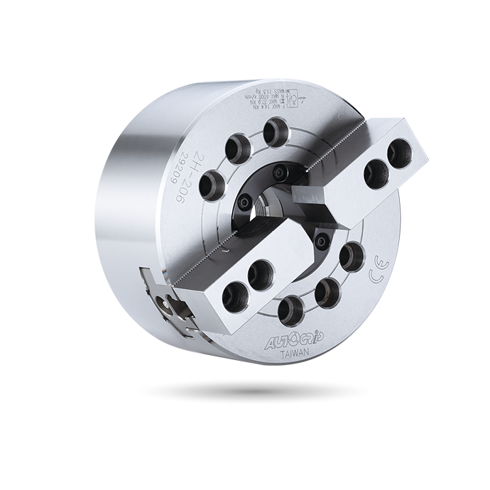
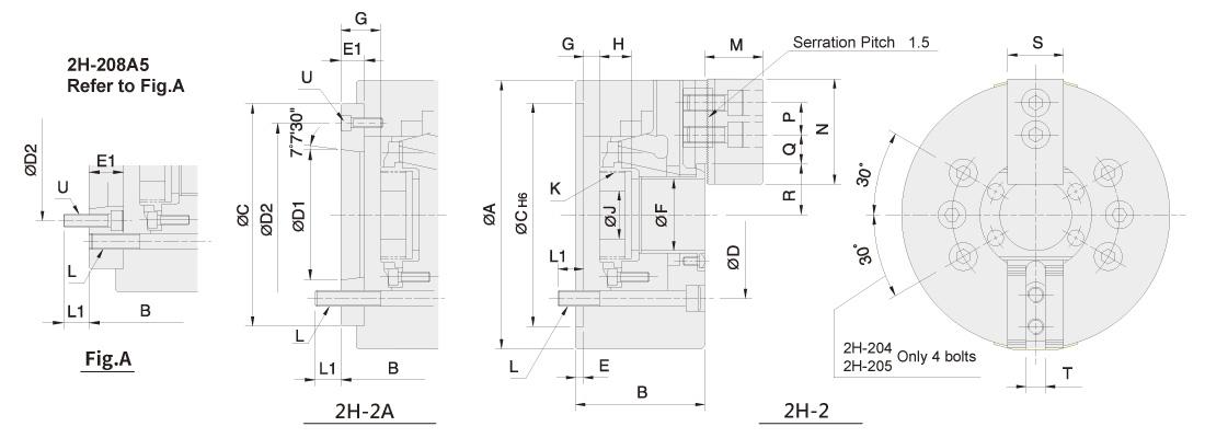
2H-2/2H-2A
LARGE THRU-HOLE POWER CHUCK
LARGE THRU-HOLE | 2-JAW
- WEDGE-HOOK type 2-jaw with the extra large through-hole.
- Matching surfaces of all parts hardened, ground and lubricated directly.
- High rigidity and high repeatability precision.
J is the hole diameter of blank draw nut,
If not notified, Autogrip will adopt the K Default as K value.
K max is the maximum thread specification, and it could be customize.
Specifications
| Model |
- |
Thru-hole
(mm) |
Plunger
stroke
(mm) |
Jaw stroke
(Dia.)
(mm) |
Chucking
Dia. Max.
(mm) |
Chucking
Dia. Min.
(mm) |
Max. D.B.
pull
kN (kgf) |
Max.
clamping
force
kN (kgf) |
Max. speed
min-1 (r.p.m.) |
I
kg‧m 2 |
Weight
(kg) |
Weight
(kg) |
Matching cyl. |
Max. pressure
MPa (kgf/cm2) |
| 2H-204 |
A4 |
32 |
13 |
5.5 |
113 |
7 |
9.2
(940) |
19.4
(1980) |
8000 |
0.012 |
4.2 |
4.8 |
TK-A528 |
1.3(13) |
| 2H-205 |
A4 |
39 |
13 |
5.5 |
138 |
10 |
11.4
(1167) |
32
(3260) |
7000 |
0.02 |
6.8 |
7.6 |
TK-A533 |
1.6(16) |
| 2H-206 |
A5 |
53 |
14 |
6 |
170 |
13 |
15.5
(1580) |
44.4
(4530) |
6000 |
0.06 |
13.1 |
14.9 |
TK-A646 |
1.6(16) |
| 2H-208 |
A5 |
66 |
18 |
7.6 |
210 |
17 |
23.1
(2360) |
57.3
(5840) |
5000 |
0.17 |
21.3 |
24.2 |
TK-A853 |
1.8(18) |
| 2H-208 |
A6 |
66 |
18 |
7.6 |
210 |
17 |
23.1
(2360) |
57.3
(5840) |
5000 |
0.17 |
21.3 |
22.4 |
TK-A853 |
1.8(18) |
| 2H-210 |
A8 |
86 |
21 |
8.9 |
260 |
17 |
23.1
(2360) |
87.7
(8943) |
4500 |
0.31 |
33.5 |
36.2 |
TK-A1075 |
2.2(22) |
* The 2H-2A's dimensions and specifications are shown in the orange data .
* The 2H-2 series are power chucks with extra large thru-hole design.
* The rotary cylinders are recommended based on power chucks that from are common used in the industry.
* If you find that you need different bore size or installation interface, please just contact us. We have many standard and customized rotary cylinders for option and meet your needs.
Dimensions
| Model |
- |
A |
B |
B |
C |
D |
D1 |
D2 |
E |
E1 |
F |
G max. |
G max. |
G min. |
G min. |
H |
J |
K max. |
K Default |
L |
L1 |
L1 |
M |
N |
P |
Q max. |
Q min. |
R max. |
R min. |
S |
T |
U |
| 2H-204 |
A4 |
113 |
59 |
83 |
85 |
70.6 |
65.31 |
82.6 |
4 |
28 |
32 |
3.5 |
31.5 |
-9.5 |
18.5 |
17.5 |
12 |
M38x1.5 |
M32x1.5 |
4~M10 |
16 |
15 |
24 |
52 |
14 |
12.75 |
6.75 |
25 |
22.25 |
23 |
10 |
3~M10 |
| 2H-205 |
A4 |
138 |
60 |
71 |
110 |
82.6 |
65.31 |
96 |
4 |
15 |
39 |
1 |
16 |
-12 |
3 |
20 |
12 |
M45x1.5 |
M40x1.5 |
4~M10 |
15 |
15 |
31 |
62 |
14 |
20.25 |
6.75 |
29.5 |
26.75 |
25 |
10 |
3~M6 |
| 2H-206 |
A5 |
170 |
81 |
91 |
140 |
104.8 |
82.56 |
116 |
5 |
15 |
53 |
13 |
28 |
-1 |
14 |
17.5 |
20 |
M60x2 |
M55x2 |
6~M10 |
16 |
16 |
37 |
73 |
20 |
22.75 |
9.25 |
36 |
33 |
31 |
12 |
3~M6 |
| 2H-208 |
A4 |
210 |
91 |
109 |
170 |
133.4 |
82.56 |
104.8 |
5 |
23 |
66 |
16.5 |
39.5 |
-1.5 |
21.5 |
20 |
30 |
M75x2 |
M60x2 |
6~M12 |
17 |
18 |
38 |
95 |
25 |
23.7 |
10.2 |
45.7 |
41.9 |
35 |
14 |
6~M10 |
| 2H-208 |
A6 |
210 |
91 |
103 |
170 |
133.4 |
106.38 |
150 |
5 |
17 |
66 |
16.5 |
33.5 |
-1.5 |
15.5 |
20 |
30 |
M75x2 |
M60x2 |
6~M12 |
17 |
15 |
38 |
95 |
25 |
23.7 |
10.2 |
45.7 |
41.9 |
35 |
14 |
3~M6 |
| 2H-210 |
A8 |
260 |
102 |
115 |
220 |
171.4 |
139.72 |
190 |
5 |
18 |
86 |
10.5 |
28.5 |
-10.5 |
7.5 |
25 |
45 |
M95x2 |
M85x2 |
6~M16 |
20 |
22 |
43 |
110 |
30 |
32.2 |
12.7 |
56.5 |
56.5 |
40 |
16 |
3~M8 |
* The 2H-2A's dimensions and specifications are shown in the orange data .
Download
| Model |
2D pdf |
2D dwg |
3D step |
| 2H-204 |
|
|
|
| 2H-204A4 |
|
|
|
| 2H-205 |
|
|
|
| 2H-205A4 |
|
|
|
| 2H-206 |
|
|
|
| 2H-206A5 |
|
|
|
| 2H-208 |
|
|
|
| 2H-208A5 |
|
|
|
| 2H-208A6 |
|
|
|
| 2H-210 |
|
|
|
| 2H-210A8 |
|
|
|
4H-2/4H-2A
LARGE THRU-HOLE POWER CHUCK
LARGE THRU-HOLE | 4-JAW
- WEDGE-HOOK type 4-jaw with the extra large through-hole.
- Matching surfaces of all parts hardened, ground and lubricated directly.
- High rigidity and high repeatability precision.
J is the hole diameter of blank draw nut,
If not notified, Autogrip will adopt the K Default as K value.
K max is the maximum thread specification, and it could be customize.
Specifications
| Model | - | Thur-hole
(mm) | Plunger
stroke
(mm) | Jaw stroke
(Dia.)
(mm) | Chucking
Dia. Max.
(mm) | Chucking
Dia. Min.
(mm) | Max. D.B.
pull kN
(kgf) | Max.
clamping
force kN
(kgf) | Max. speed
min-1 (r.p.m.) | I
kg‧m 2 | Weight
(kg) | Weight
(kg) | Matching cyl. | Max. pressure
MPa (kgf/cm2) |
|---|
| 4H-206 |
A5 |
53 |
14 |
6.0 |
170 |
13 |
23.2
(2375) |
66.7
(6810) |
5000 |
0.06 |
12.5 |
16.7 |
TK-C646 |
2.5(25) |
| 4H-208 |
A5 |
66 |
18 |
7.6 |
210 |
17 |
34.3
(3500) |
85.8
(8750) |
4200 |
0.19 |
23.5 |
25.4 |
TK-A853 |
2.8(28) |
| 4H-208 |
A6 |
66 |
18 |
7.6 |
210 |
17 |
34.3
(3500) |
85.8
(8750) |
4200 |
0.19 |
23.5 |
24.3 |
TK-A853 |
2.8(28) |
| 4H-210 |
A6 |
86 |
21 |
8.9 |
260 |
37 |
49.1
(5010) |
132
(13460) |
3800 |
0.4 |
38.7 |
44 |
TK-A1075 |
3.2(32) |
| 4H-210 |
A8 |
86 |
21 |
8.9 |
260 |
37 |
49.1
(5010) |
132
(13460) |
3800 |
0.4 |
38.7 |
42.3 |
TK-A1075 |
3.2(32) |
* The 4H-2A's dimensions and specifications are shown in the orange data .
* The 4H-2A series are power chucks with extra large thru-hole design.
* The rotary cylinders are recommended based on power chucks that from 6”~8” are common used in the industry.
* If you find that you need different bore size or installation interface, please just contact us. We have many standard and customized rotary cylinders for option and meet your needs.
Dimensions
| Model | - | A | B | B | C | D | D1 | D2 | E | E1 | F | G max. | G max. | G min. | G min. | H | J | K max. | K Default | L | L1 | L1 | M | N | P | Q max. | Q min. | R max. | R min. | S | T | U |
|---|
| 4H-206 |
A5 |
170 |
81 |
91 |
140 |
104.8 |
82.56 |
116 |
5 |
15 |
53 |
13 |
28 |
-1 |
14 |
17.5 |
20 |
M60x2 |
M55x2 |
4~M10 |
16 |
16 |
37 |
73 |
20 |
21.25 |
9.25 |
36 |
33 |
31 |
12 |
3~M6 |
| 4H-208 |
A5 |
210 |
91 |
109 |
170 |
133.4 |
82.56 |
104.8 |
5 |
23 |
66 |
16.5 |
39.5 |
-1.5 |
21.5 |
20 |
30 |
M75x2 |
M60x2 |
4~M12 |
17 |
18 |
38 |
95 |
25 |
23.7 |
10.2 |
45.7 |
41.9 |
35 |
14 |
6~M10 |
| 4H-208 |
A6 |
210 |
91 |
103 |
170 |
133.4 |
106.38 |
150 |
5 |
17 |
66 |
16.5 |
33.5 |
-1.5 |
15.5 |
20 |
30 |
M75x2 |
M60x2 |
4~M12 |
17 |
15 |
38 |
95 |
25 |
23.7 |
10.2 |
45.7 |
41.9 |
35 |
14 |
3~M6 |
| 4H-210 |
A6 |
260 |
102 |
122 |
220 |
171.4 |
106.38 |
133.4 |
5 |
25 |
86 |
10.5 |
35.5 |
-10.5 |
14.5 |
25 |
45 |
M95x2 |
M85x2 |
4~M16 |
20 |
18 |
43 |
110 |
30 |
32.2 |
12.7 |
56.5 |
52.05 |
40 |
16 |
6~M12 |
| 4H-210 |
A8 |
260 |
102 |
115 |
220 |
171.4 |
139.72 |
190 |
5 |
18 |
86 |
10.5 |
28.5 |
-10.5 |
7.5 |
25 |
45 |
M95x2 |
M85x2 |
4~M16 |
20 |
22 |
43 |
110 |
30 |
32.2 |
12.7 |
56.5 |
52.05 |
40 |
16 |
3~M8 |
* The 4H-2A's dimensions and specifications are shown in the orange data .
Download
| Model |
2D pdf |
2D dwg |
3D step |
| 4H-206 |
|
|
|
| 4H-206A5 |
|
|
|
| 4H-208 |
|
|
|
| 4H-208A5 |
|
|
|
| 4H-208A6 |
|
|
|
| 4H-210 |
|
|
|
| 4H-210A6 |
|
|
|
| 4H-210A8 |
|
|
|
2H/2H-A
THRU-HOLE POWER CHUCK
Thru-Hole | 2-JAW
- WEDGE-HOOK type 2-jaw with the through-hole.
- Matching surfaces of all parts hardened, ground and lubricated directly.
- High rigidity and high repeatability precision.
J is the hole diameter of blank draw nut.
If not notified, AUTOGRIP will adopt the K Default as K value.
K is the maximum thread specification and it could be customize.
<

 Sign In